M3C2 (plugin)
Introduction
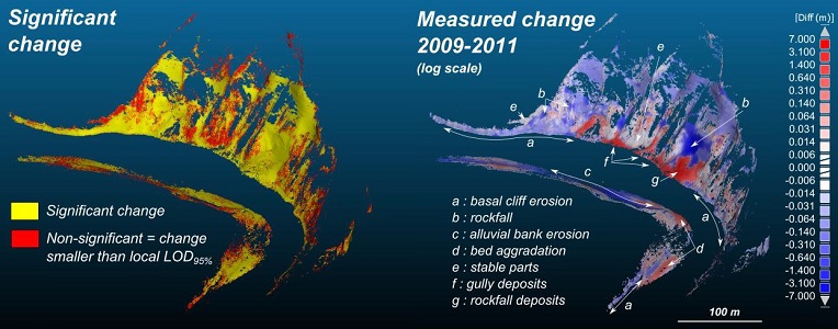
The M3C2 plugin is the unique way to compute signed (and robust) distances directly between two point clouds.
While you can use the 'Guess params' button, it is highly advised to read (even quickly) the original article by D. Lague, N. Brodu and J. Leroux (Geosciences Rennes).
Precision Maps
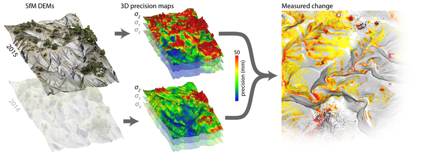
Since version 2.9, the M3C2 plugin also includes the ‘precision maps’ (M3C2-PM) variant of James et al. (2017), for when precision estimates are already available for each point, and don’t need to be calculated from roughness estimates. M3C2-PM is particularly suited to point clouds generated by photogrammetric processing; see the dedicated section below and James et al. (2017) for more details.
Computing M3C2 distances
Select the two clouds you want to compare then call the 'Plugins > M3C2 Distance' method.
Main parameters
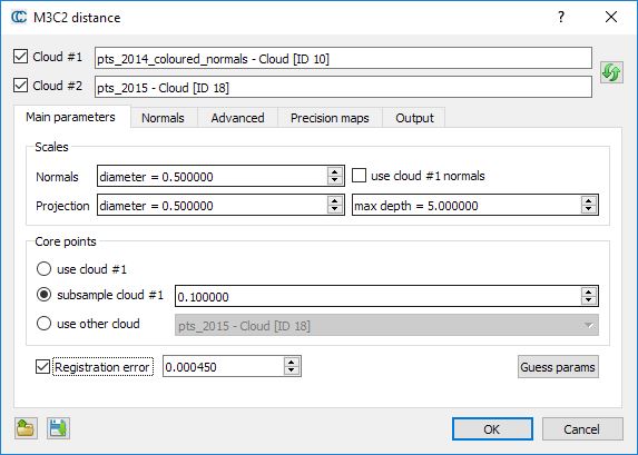
As with the CANUPO algorithm, computations can only be done on particular points - called core points - in order to speed up the computations. The main idea is that while TLS clouds are generally very dense, it is not necessary to measure the distance at such a high density (and it would very slow in practical). This is why the user has to choose what 'core points' will be used (lower part of the dialog):
- either the whole cloud
- or a sub-sampled version of the input cloud
- or eventually a custom set of core points (typically a previously sub-sampled version of the input cloud, or a rasterized version)
The other important parameters are the normal and projection scales:
- the normal scale is the diameter of the spherical neighborhood extracted around each core point to compute a local normal. This normal is used to orient a cylinder inside which equivalent points in the other cloud will be searched for. Regarding normals more advanced options can be set in the 'Normals' tab (see below).
- the projection scale is the diameter of the above cylinder.
- the max depth parameter simply correspond to the cylinder height (in both directions)
Note: the bigger those radii are, the less local surface roughness (and noise) will have an influence. But also the more points will be 'averaged' and the slower the computation will be.
Eventually, if you now the global registration error (if your cloud has been generated by registering several stations typically) you can input it in the 'registration error' field. It will be taken into account during the confidence computation for each point (that let you know if the corresponding displacement is significant or not).
Normals
Using 'clean' normals is very important in M3C2. The second tab let you specify more advanced options regarding their computation:
- Default: the normals are computed thanks to the normal scale parameters defined in the previous tab
- Multi-scale: for each core points, normals are computed at several scale and the most 'flat' is used
- Vertical: no normal computation is done, only purely vertical normals are used (perfect for 2D problems)
- Horizontal: normals are 'constrained' in the (XY) plane
Alternatively you can also use the cloud original normals (if any) by checking the use cloud #1 normal checkbox on the first tab.
The 'orientation' options let you help the plugin to properly orient the normals:
- either by specifying a global orientation (relatively to a given axis or a particular point)
- or by specifying a cloud containing all the sensor positions
Precision maps
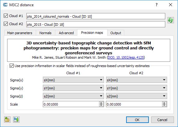
The Precision maps tab enables the calculation of detectable change to be carried out using measurement precision values stored in scalar fields of point clouds, rather than being estimated from roughness calculations.
This ‘PM’ variant of M3C2 is described in James et al. (2017) and allows photogrammetric precision estimates to be used directly within the M3C2 workflow.
If scalar fields are available, then the check box can be used to enable the ‘precision maps’ variant of M3C2. In this case, uncertainty estimates will no longer be made from roughness estimates at the projection scale in the Main Parameters tab, but will be based on 3-D point precision estimates stored in scalar fields. Ensure that the appropriate scalar fields are selected for both point clouds to describe measurement precision in X, Y and Z (sigmaX, sigmaY and sigmaZ).
The scale can be changed if the precision values are in different units to the point coordinates. For example, if point coordinates and precision values are in metres, then the scale value is 1.000. However, if coordinates are in metres, but the scalar fields of precision are provided in millimetres, then the scale value should be set to 0.001.
Advanced
The 'Advanced' tab contains... advanced parameters. Their name should speak for themselves. They can be ignored by most users.
Output
You can choose to generate additional scalar fields and also on which cloud the measurements should be re-projected (especially useful if you use core points different from the first input cloud).
Save/load parameters
Note: Parameters can be saved (and re-loaded) via dedicated text files. Use the two icons on the bottom-left part of the dialog to do this.
Computing distance
When ready, simply click on the "OK" button. Once finished, the dialog will be closed. You will generally have to hide the input clouds to see the result (generated in a new cloud).
Note that in addition to the distances, the M3C2 plugin generates several other scalar fields:
- distance uncertainty (the closer to zero the better)
- change significance (whether the distance probably correspond to a real change or not)
- and optionally the standard deviation and number of neighbors at each core point (as specified in the 'output' tab)
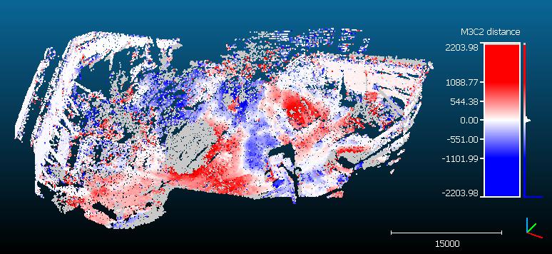
Note also that points without any corresponding points in the other cloud stay in 'gray' (they are associated to NaN - not a number - distances). This means that no points in the other cloud could be found inside the search cylinder. Therefore, gray points means that either some parts of the clouds have no equivalent in the other cloud (due to hidden parts or other holes in the datasets) or simply that the cylinder maximum length is not long enough!
For a clearer display, you should create your own absolute color scale, with you own labels, etc. Use the Color Scales manager to do it.
