Entity properties
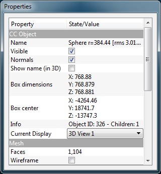
When a single entity is selected, its properties are accessible in the ‘Properties’ dialog (on the left side below the DB tree by default).
Most of the entities display properties can be set via this dialog:
- visibility of the entity
- visibility of its features (colors, normals, etc.)
- the current 3D view in which the entity is displayed (‘Current Display’ list)
- the active scalar field and its display parameters (current color scale, whether it should be displayed in the 3D view and how, etc.)
- etc.
Other parameters can be modified such as
- ‘wireframe’ or ‘stippling’ – a kind of fake transparency – modes for a mesh for instance
- primitives parameters
- etc.
And of course various pieces of information:
- bounding-box center and extents
- the number of points or triangles
- the ‘Global shift and scale’
- associated meta-data
- etc.
There are even some action buttons sometimes (for viewport or sensor entities for instance).
Scalar field display parameters editor
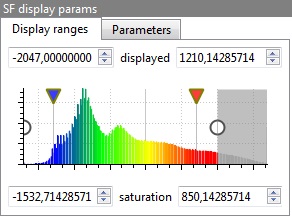
In the Properties dialog, an editor very specific to CloudCompare can be found on clouds and entities with an active scalar field:
This editor lets the user set most of the display parameters of the active scalar field in a very concise way (in addition to get a quick overview of the scalar field histogram):
- use the left and right white circles to set the min and max displayed scalar values. Below and above those values, the points will either appear in grey or won’t appear at all (depending on the parameter ‘show NaN/out of range values in grey’ that is accessible in the ‘Parameters’ tab). This way the user can quickly hide points with values outside a given interval, in order to focus on the other points for instance.
- use the red and blue down arrows to set the min and max saturation values (to set the start and end of ‘relative’ color scales – see the Color Scales Manager)
- set additional parameters with the ‘Parameters’ tab (log or symmetrical scale, etc.)
Show normals as lines
Since version 2.13.beta, one can display the normals of a point cloud as lines:
The user can choose the lines length (same units as the cloud), as well as pick one color from a few standard ones (yellow, red, blue, etc.).
It's especially 'readable' when used with the EDL shader.
Point size and line width
Point size (for clouds) and line width (for polylines) can be set for each entity via the dedicated parameter in the entity properties.
However, one can set the default point size and default line width per 3D view. This can be done via 'interactors' that appear when the mouse hovers the top-left corner of the 3D view:
Since version 2.9, default point size and line width can range from 1 to 16 pixels (only the default point size could be set in previous versions, with a maximum size of 10 pixels).


